


Frame systems require very tight tolerances in length and height and strength to meet both national and local building regulations for timber frame buildings. CAD system is crucial for the frame design and engineering related examination such as centre of mass and resistance, torsion for components of moment frames, braced frames, shear walls, etc.
Buildings experience different forces from vertical and horizontal direction when seismic action hit them. In order to avoid catastrophic damage, the structural elements of a timber frame building include columns, beams, shear walls and floor and roof structural parts have to be placed sufficient amount in right balancing position as a basic skeleton of the building.
Modern sophisticated CAD system with our in-house engineers can analyse the safe level of skeleton structure to prevent serious damage when seismic action or avoid force hit a building. When the skeleton system is very complex and beyond our knowledge, we work with dedicated structural engineers of our partner to implement the analysis and the design.
| click to enlarge |
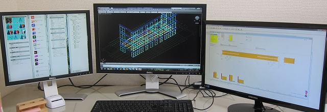 |
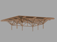
| BIM-3D cad |
 |
| BIM-3D cad |
 |
 |
 |
![]()
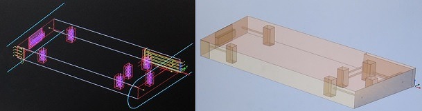
| We closely work with our client to obtain the project information. It is very important to the basic information e.g. floor plan, elevation, sectional diagram, wood species, solid or glulam, wood quality, finish, site requirements. All the specification affects the price of your frame. We initially design your frame along with your project specification to estimate total budget and lead time. Then we proceed to the next step. |
![]()
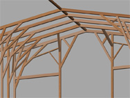
| Once you selected us as your partner for design and crafting the frame component on your project, we check and review the frame plan to clarify if the initial design is right plan for the project. Generally, some optional plans are shown in the process and its helps your cost reduction.In order to help succeeding your project we examine and revise from many aspects such as strength examination, craft simulation, 3D-modeling check, adding or removing frames to create best frame plan at better price.We operate two different CAD systems to design your timber frame. The cad system can provide 3D perspective solutions, frame layout, list of components, and then contribute to minimize material waste.toaCAD With the purpose of design for an ordinary-scale residential house and a relatively small-scale commercial project, we operate toaCAD. hsbCAD We use hsbCAD for complex wood-craft joint and heavy timber construction connected by custom made metal fitters as design tool for custom cut frame design. Usually, CNC machines e.g. Hundegger or Hand craft joinery. cadwork We use cadwork for complex wood-craft joint and heavy timber construction connected by custom made metal fitters as design tool for custom cut frame design. Usually, CNC machine which import BTL format e.g. Routech a 6axis cnc centre or Hand craft joinery |
![]()
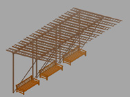
| Before the component data is transferred to the cam data, we carry out an inspection each frame plan by well experienced engineering staff for rising work. Position of joints, metal fitters, anchor bolts of foundation must be no intervention for rising, for instance. |
| click to enlarge |
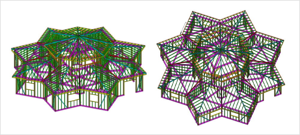 |
| 3D modeling |
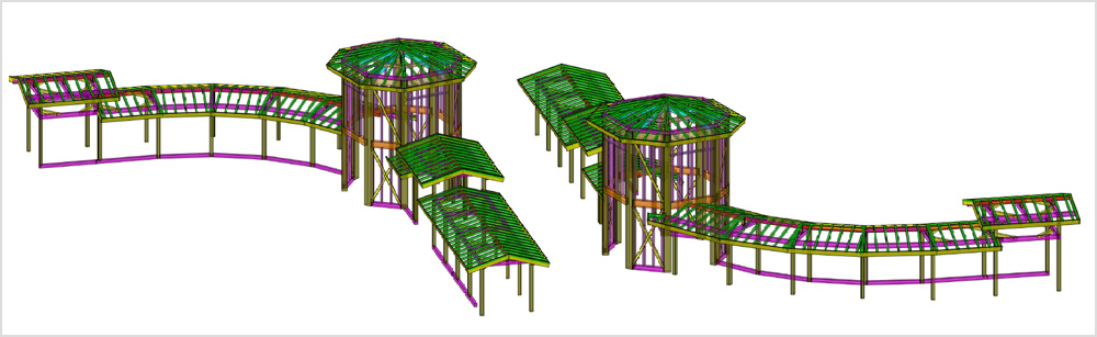 |
| 3D modeling |
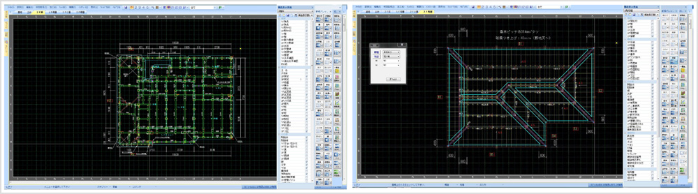 |
| frame plan |